Realtime realistic snow deformation
Games like Red Dead Redemption 2 and Horizon Forbidden West are wonderful games, where you can just fall in love with the scenery of the worlds. Even better is the interaction that the player or AI of the game can perform. One of those interactions I took a closer look at, is the deformation of terrain. Snow to be exact. Taking a look at what RDR2 outputs, I was able to recreate Rockstar’s snow deformation to some extent and I will show how I achieved such.
Deforming the terrain using depth
📝 Note: A depth pass is a graphics pass that is used to get the depth. A depth pass is like a regular pass, but the pixel shader does not assign colors to a render target.
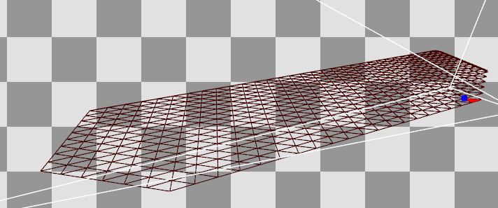
To get the deformed data of the terrain, the most optimal way of getting the height data is using depth from the point of view of the terrain. I use a orthographic render from underneath the terrain. That way, I can get a value from 0 to 1, so I can calculate the offset for the terrain. To do this accurately, an orthographic projection is needed to get the accurate depth from the terrain to the mesh. How that would look like can be seen in the following image:
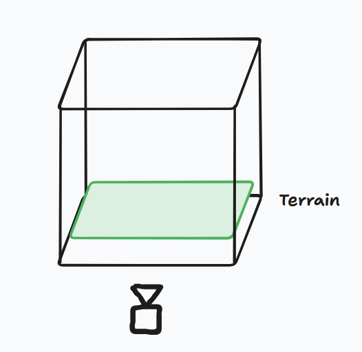
The only issue when using this approach is, that this would only work if the terrain mesh if completely flat. I do not take the height into account of the geometry, which means, that the offset would not be accurate.
To enable taking the height into account, I also performed a depth render on the base terrain as well. This allowed me to determine the offset of the height scale that was obtained from the depth render of the depth pass, resulting in accurate data with almost any terrain mesh.
Since I rely on a depth render of geometry, I can easily add the functionality that the skinned meshes in the scene, can also influence the terrain with the animation that is running for the skinned meshes. This introduces more realism into the terrain, since the footsteps of a person for example are tracked precisely on the terrain. The only thing that we need to do is utilize the vertex shader of the skinned pipeline. This enables the possibility to track the depth from the skinned meshes in-pose.
Compute the missing data
📝 Note: “A Compute Shader is a Shader Stage that is used entirely for computing arbitrary information. While it can do rendering, it is generally used for tasks not directly related to drawing triangles and pixels (General Purpose).” – The Khronos Group, https://www.khronos.org/opengl/wiki/Compute_Shader
To ensure that all the geometry data is present and valid, I utilized a set of compute shaders. These are used for the offset that is described in ‘Depth’, smoothening out the offset to remove hard edges, and to calculate the normal vectors for the geometry.
Offset
As mentioned above, it is desirable to not have a flat plane as the terrain mesh. Since the orthographic depth render returns a depth based on a plane, we need to offset the depth, so the snow deforms at the correct height. This only requires two texture reads from the depth of all the meshes and the terrain. Then we subtract the terrain height from the height of the depth map from the meshes and divide it by the snow height.
Code.
Does this pass have to be a separate compute pass, maybe. You can snug it in another of these compute passes and save some memory on the graphics card, but I decided to do it this way, to have a foundation for a new feature. More will be explained in Future work.
Smoothening
After the application of the offset, the terrain depth map was smoothened by the application of a blur over the terrain depth map. This blur removes the sharp transitions within the depth that was rendered giving the terrain a more smooth look and more accurate shading.
In my implementation, I used a Gaussian blur with a 5x5 kernel. This blur gives me a very nice blurred effect on the depth map, where it improves the shading significantly. All, while the blur remains cheap, with some optimizations (seen after the normal calculation pass). The differences can be seen below between the use of no blur and the use of the Gaussian blur.
Normal calculation
When we are offsetting our terrain in height, the normal data we have, will become invalid. A new normal needs to be calculated based on the terrain depth map. This can be done in the pixel/fragment shader of the terrain rendering, but I decided to utilize some optimizations that are available in the compute shader.
What we are essentially doing is taking the central derivative of the height neighbours. We subtract the right from the left and the bottom from the top in ‘texture space’.
In code, it should look something like this:
Language: HLSL
 float du = Src[dispatchID.xy + uint2(-1, 0)] - Src[dispatchID.xy + uint2(1, 0)];
 float dv = Src[dispatchID.xy + uint2(0, -1)] - Src[dispatchID.xy + uint2(0, 1)];
 float deformation = Src[dispatchID.xy + uint2(0, 0)];

 float3 normal = mad(normalize(float3(du, -dv, 0.1)), 0.5, 0.5); //-dv for my left-handed, z-up world. also transformed to 0..1
In the pixel shader, I blend the normal of the normal map or the vertex normal with the calculated normal using the UDN method. This method results in the correct normal for the mesh I used, which allowed me to have the correct normal for the mesh I am using and that will allow me to have height differences in my mesh for shading purposes.
Language: HLSL
float3 normal = IN.Normal;

if (Material.HasNormal)
{
    float3 normalSample = mad(Normal.Sample(Sampler, IN.TexCoord).rgb, 2.0f, -1);
    float3x3 TBN = float3x3(IN.Tangent, IN.BiNormal, normal);
    normal = normalize(mul(normalSample, TBN));
}

// Normal blending: https://blog.selfshadow.com/publications/blending-in-detail/ (UDN Blending)
normal = normalize(float3(normal.xy + IN.DeformedNormal.xy, normal.z));
Since I utilize compute shaders for these passes, I am able to steer the GPU in the correct direction. I have more tools at my disposal to make sure the compute shader can be as efficient as it can be. One of these tools I have used to gain speed, is the use of shared memory. Shared memory is a small bank of memory that is similar to the L1 cache in the GPU. The only thing I need to do, is tell the compiler I am going to use that memory. This is also why the shared memory is know as manual caching.
Since the data required to fetch is closer to the core of the GPU, rather than being in L2 cache or even worse, VRAM, we gain time.

To use the shared memory, we need to declare a variable in our shader and use a certain keyword to instruct the compiler that those values are stored in shared memory. In HLSL, this is called groupshared and in GLSL, this is called shared. Since this memory is on cache level, the memory available for use is not that big either. You get a small buffer per group which depends on the GPU in question.
I applied the use of the shared memory to the calculation of the normals. For the calculation of the normals I need to do multiple texture taps on sometimes the same data. So for this scenario, it is a great fit for the use of shared memory. The code below shows how I make use of shared memory, and how I prevent extra texture taps by loading the data in shared memory in advance.
Language: HLSL
groupshared float localDataShare[GROUP_SIZE + 2][GROUP_SIZE + 2];

// ...

if (groupThreadID.x < (GROUP_SIZE + 2) / 2 && groupThreadID.y < (GROUP_SIZE + 2) / 2)
{
    float2 uv = float2(dispatchID.xy) / (float) width + groupThreadID.xy / (float) width;
    float4 sample = Src.Gather(Sampler, uv);

    localDataShare[groupThreadID.x * 2][groupThreadID.y * 2] = sample.w;
    localDataShare[groupThreadID.x * 2][groupThreadID.y * 2 + 1] = sample.x;
    localDataShare[groupThreadID.x * 2 + 1][groupThreadID.y * 2] = sample.z;
    localDataShare[groupThreadID.x * 2 + 1][groupThreadID.y * 2 + 1] = sample.y;
}

GroupMemoryBarrierWithGroupSync();

int2 ldsId = groupThreadID.xy + int2(1, 1);

float du = localDataShare[ldsId.x - 1][ldsId.y] - localDataShare[ldsId.x + 1][ldsId.y];
float dv = localDataShare[ldsId.x][ldsId.y - 1] - localDataShare[ldsId.x][ldsId.y + 1];
float deformation = localDataShare[ldsId.x][ldsId.y];
One last thing to note about synchronization. If the threads that need to wait for data from a texture, the others might already try to read the shared memory, while it is not populated. That is why I made use of the GroupMemoryBarrierWithGroupSync() function, to ensure that all the shared memory is populated with the corresponding data.
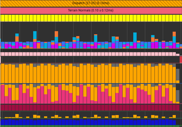
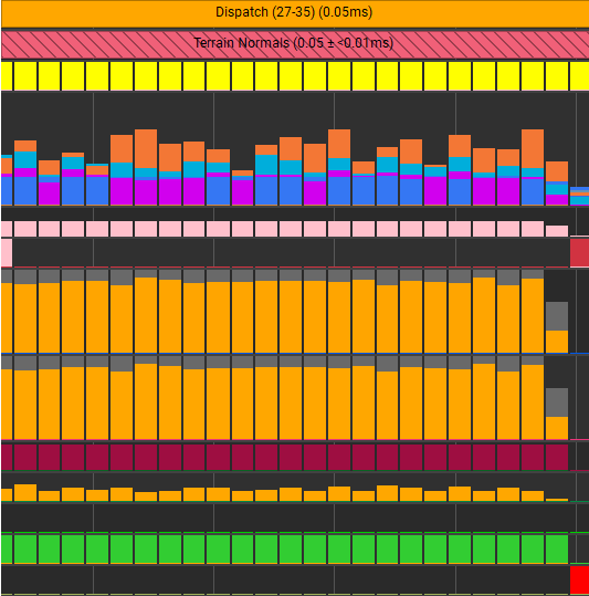
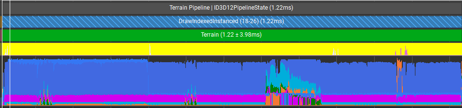
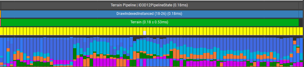
I profiled the differences between the use of shared memory and just regular texture reads using Nvidia Nsight, and it shows that I was able to shave off 50% of my time spent in this compute shader. And to verify that it was using the shared memory, Nsight showed that the throughput of shared memory was used and replaced a lot of the VRAM and L2 cache throughput.
Extra details
“Tessellation is the vertex processing stage, where patches of vertex data are subdivided into smaller primitives.” – The Khronos Group The most important part of the terrain. The part that will be visible. Because of the offset I take into account, I am able to create meshes in Blender and I am able to have cool looking and more important, realistic looking terrain. The mesh of the terrain will be of a lower resolution, because we will add more vertices to the mesh using the tessellation shaders we have at our disposal. The tessellation shaders are very good at adding more vertices, but they cannot reduce the amount of vertices. They can only discard them. Luckily, I was still able to make a simple distance-based LOD system, that keeps the default mesh if the terrain part is far away, while the parts that are close are being tessellated to add more detail to the mesh. The function that I used is similar to the light attenuation function, which reduces the LOD over distance.
Since the tessellation shaders allowed me to discard vertices, one very known technique can be used to speed up the rendering of the terrain. The technique in question is called ‘view frustum culling’. I apply this form of culling in the hull shader, where we instruct the tessellator how the mesh will be tessellated. If the entire triangle is outside of the view frustum, it discards the triangle. Else, the LOD algorithm as described above is applied and we render the triangle.
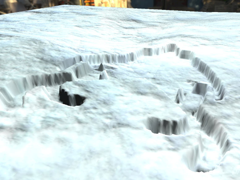
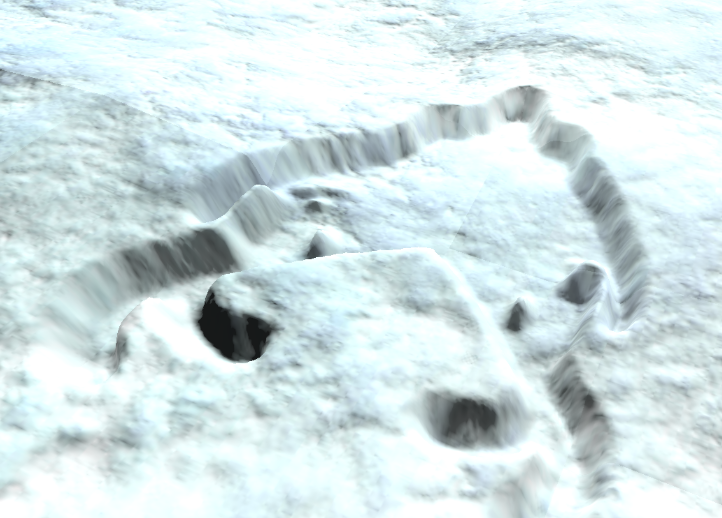
Even though, I added some branches in my shader code, I was still able to gain some performance using these two optimization techniques, as seen by the profiler. Even the distance-based LOD system did its magic, by decreasing the amount of unnecessary triangles that would not make a difference for the terrains appearance. After utilizing all the mentioned techniques, I obtained a terrain that looks something like this, which which is fully functional.
If I take this terrain and put it in a game, would this hit the mark for current standards? I would say that this feature is definitely usable, but you can enhance and optimize the terrain even more.
Recommendations for future work
I created this project in 8 weeks. Since I am at this point of writing this post, not a very experienced graphics programmer, I was not able to complete this deformation system to what I would liked it to be. Some of these aspects are more for looks and features, and others are to optimize the speed of this system.
Culling
At the moment, I do a depth pass for every mesh in the scene. To make sure the rasterizer will not get blown by it needing to rasterize every mesh per terrain, some culling can be applied on the CPU-side to reduce the renders per mesh to 4 renders(if we have the terrain laid-out in a grid), which will save some GPU time. Since there is an orthographic projection, an AABB collision check can be done to see if the mesh is above the terrain, and thus needs depth testing.
Snow refill
The weather is one of the major variables of this system. If it is snowing, the deformation should gradually restore itself. I wanted to utilize the offset compute shader to store this refill for the terrain. I still need to figure out on how I would deform the snow again after the snow has been refilled.
Mud/Sand equivalent
I made this project with snow as an example, but one could make some alterations and make this system work for mud or sand. Even for more loose sand, an edited smooth step function can be used to make the sand ‘fall’ in the correct place. Change the material and we have some mud or sand in our world.
Same for this resource, the weather can affect this terrain as well. If it rains, we would like to have water puddles as well. This can be achieved by raising a water mesh through the terrain. Since the actual geometry of the terrain is lower than the water mesh, the water mesh becomes visible. Then one can apply magic on the water mesh, such as rain or wind affecting the water, creating more realism.
Parallax Occlusion Mapping
The last thing that could be done to enhance the terrain even more, is apply parallax occlusion mapping. How I visualized to use POM to enhance the terrain, is not to use it for the deformation itself, but for something like foliage inside of the terrain.
References:
- Real-time Snow Deformation, Daniel Hanák, 2021: https://is.muni.cz/th/m2v6i/real-time_snow_deformation.pdf
- Optimizing GPU occupancy and resource usage with large thread groups, Sebastian Aaltonen, 2017: https://gpuopen.com/learn/optimizing-gpu-occupancy-resource-usage-large-thread-groups/
- UDN normal blending: https://docs.unrealengine.com/udk/Three/MaterialBasics.html#Detail%20Normal%20Map